| Home | Lighting Control | Micro Fusion | Electricity | Climate Change | Contacts | Links |
|---|

Introduction:
The Alumina Cylinder is a key component of a Micro Fusion Unit. Micro Fusion International Ltd. is open to supplier suggested design changes that can reduce unit costs for large scale manufacture.
These specifications are for discussion and quotation only. There may be minor specification changes before an order is issued. Please provide estimated prices for 1, 10 and 100 units.
General:
1. The Alumina Cylinder is a thick wall cylinder made of non-porous vacuum tight high purity controlled resistivity alumina. It must have a working life of at least 20 years.
2. In operation it must be completely leak free as measured with a helium leak detector.
Pressure:
3. The Alumina Cylinder operates with a high vacuum on the inside that is maintained by constantly running vacuum pumps. The Alumina Cylinder is subject to an external oil pressure that is normally in the range 50 to 130 psig and that under pressure vessel test conditions reaches 200 psig.
4. The Alumina Cylinder and its end seals must not crack, deform, degrade or otherwise fail during the pressure vessel test.
Dimensions:
5. All dimensions are measured at room temperature (23 degrees C).
6. The Alumina Cylinder is symetric about its main axis.
7. The Alumina Cylinder must be round, not oval shaped.
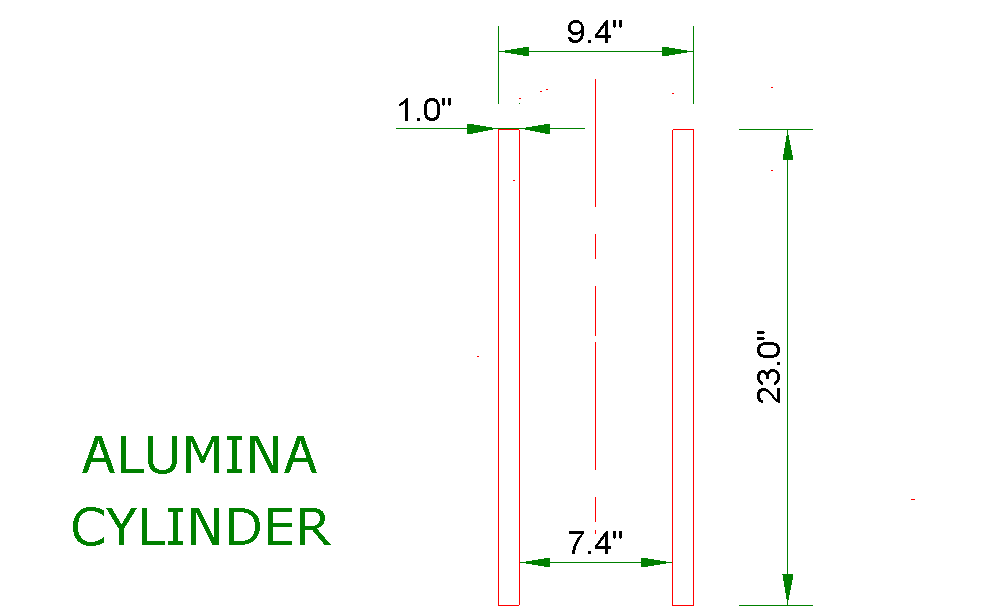
8. The nominal length of the Alumina Cylinder is 584.2 mm (23.0 inches).
9. The tolerance on the overall length of the Alumina Cylinder is +/- 2.0 mm.
10. Within 10 mm of the cylinder ends the OD is machined to 239 mm (9.4 inches) +/- 1.0 mm. A straight line connecting the center of the top OD circle to the center of the bottom OD circle defines the axis of the Alumina Cylinder.
11. The nominal outside radius of the Alumina Cylinder with respect to the axis is 119.4 mm.
12. Except near the cylinder ends the outside radius tolerance with respect to the cylinder axis is +/- 2 mm.
13. The nominal inside radius (IR) of the Alumina Cylinder with respect to the cylinder axis is 94 mm (3.7 inches) throughout the entire length of the Alumina Cylinder.
14. The tolerance on the cylinder IR is +/- 1.0 mm.
15. The Alumina Cylinder top face must be normal to the axis and highly polished to achieve a good high vacuum seal to a gold O ring.
16.The Alumina Cylinder bottom face must be normal to the axis and highly polished to achieve a good high vacuum seal to an elastomeric oil resistant O ring.
17. The end surfaces must be locally smooth to less than 8 micro inches. It may be necessary to apply a metal coating to the end faces to achieve the required degree of smoothness. This coating must be long term stable up to at least 320 degrees C.
18. The end faces must be flat to within +/- .001 inch across the entire face.
19.The end faces must be normal to the cylinder axis within an angle of .002 radians.
20.It may be necessary to make a very small radius on the Alumina Tube end face corners to prevent local stress concentration.
Material:
21. The alumina material must be Wesgo AL-300 or equal with a small amount of resistivity control compound added.
22. The material Flexural Strength must be at least 272 MPa.
23. The Young's Modulus should be 51 to 54 MSI.
24. The thermal conductivity should be 22 to 27 W / m-K.
25. The thermal coefficient of expansion should be 7.3 to 7.4 X 10^-6 / degree C from room temperature to 320 degrees C.
26. The DC electrical volume resistivity at room temperature should be at least 10^14 ohm-cm. The DC electrical volume resistivity at 315 degrees C should be at least 5 X 10^11 ohm-cm.
27. The dielectric strength should be at least 697 DC volts / mil.
Performance:
28. The Alumina Cylinder design is intended to keep the material axial stress under 1000 psi under maximum test pressure conditions. The end forces must be evenly distributed over the Alumina Cylinder end faces to achieve this objective.
29.In operation the Alumina Cylinder is subject to about 5 kWt of axially non-uniform heating from the inside. Under steady state conditions this heat is transported by thermal conduction through the alumina material to the external oil bath.
30.The Alumina Cylinder must withstand the consequent thermal stresses.
31. One end of the Alumina Cylinder is subject to a constant axial DC electric field of about 100,000 volts per inch. The alumina material must withstand this electric field without breakdown, conducting or cracking.
32. It is anticipated that the alumina operating temperature will normally be as much as 315 degrees C. The decrease in the electrical resistivity of the alumina at that temperature is an issue of concern.
End Seal Details:
33. The Alumina Tube end face O-ring gaskets will be compressed between the flat alumina end faces and machined metal end faces. In order to keep the alumina end face stress uniform the alumina end faces and the metal end faces must both be machined flat, except for the O ring groove.
34. The metal end faces have a raised ring with an inside diameter slightly greater than the Alumina Cylinder end OD to permit accurate positioning of the Alumina Cylinder with respect to the metal ends.
Long Term Degradation:
35. The issue of long term degradation of the Alumina Cylinder and its gaskets due to continuous exposure to a high electric field, high pressure, high temperature and ionizing radiation is currently under study. Every effort is being made to minimize this problem.
This web page last updated January 19, 2009
| Home | Lighting Control | Micro Fusion | Electricity | Climate Change | Contacts | Links |
|---|